Vector graphics plotter
UPDATE:
The code has been significantly changed to be compatible with Processing 2.1.1. Also, some functionality has been added. It can now support "translate" transformations and "rect" paths. "polygon" paths and "matrix" transformations are not yet implemented, but might be eventually. The hardware has been slightly modified: better pen holder, removed unnecessary resistorsIt was a golden day, that day I finally got up the courage to click the "add to cart" button, electronically plucking a little arduino off a hook and placing it in my empty cart. My first microcontroller needed a first project: to get some stepper motors moving on the skeleton of a long dead printer. Here follows the tale of that adventure.
First, I'll show you the result for motivation.
Junk (the hardware):
- Olde Epson printer: frame, two stepper motors, motor driver circuitry
- CD player: The laser head moving mechanism
- Desktop compy PSU as a 5V power supply
- One H-bridge - SN754410NE
- Some resistors
- Bits of wire and a small breadboard
- Arduino uno, computer and pen
- On the computer: Reads an SVG file(a common vector graphics file) and turns the path data into a series of coordinates. Then it sends the coordinates via USB to an arduino.
- On the arduino: Receives coordinate data from USB and tells the motors to move.
Starting from the printer side, here you can see the frame, pen moving mechanism and motor driver board.

Moving on to the driver board, here you can see half of the main circuit board from the printer:


Yes, I simply snapped the board in half. Why? I didn't want any of the other stuff on the board interfering. On the component side(right picture) you can see those two beautiful stepper motor driver ICs along with diodes for each wire and a power capacitor. Those wires go to the motors.
On the other side(left picture) you can see a mess of wires that is the splayed end of a printer(parallel) cable. Notice that most of them are simply connected to ground. These were intended to connect to ground in the actual printer. Who knows why they bothered to put so many in the cable. The parallel port has 25 pins, but there were 30-something wires. Anyway, 8 wires are carefully soldered to pins on the ICs. See the schematic below for details. You can also see a variety of surface mount resistors and capacitors. Most of these are used by the ICs. The thick red wires go to the 5V power supply(not the arduino power supply!)
Tutorial tip
Tutorial tip
- You probably won't have the same printer as I, but any old printer will have stepper motors. There are two main types: unipolar and bipolar. A quick google search will provide many good descriptions. If you get unipolar, they are way easy to use and you won't need such complicated circuitry. If you get bipolar, don't cry, bipolar have better torque and accuracy, but you'll either need a stepper motor driver(such as you may find on the printer's circuit board) or some H-bridges. Again, there are many good pages already made on the subject, so google it.
Here is the schematic taken out of the printer's service manual(click to enlarge):

If you are trying to do this, just look for keywords like "phase" and "enable". These are the pins you need. Everything else is just details. By the way, each enable turns on one of the two coils in the motor. Phase determines the direction of current flow in the coil. Google "bipolar stepper motor".
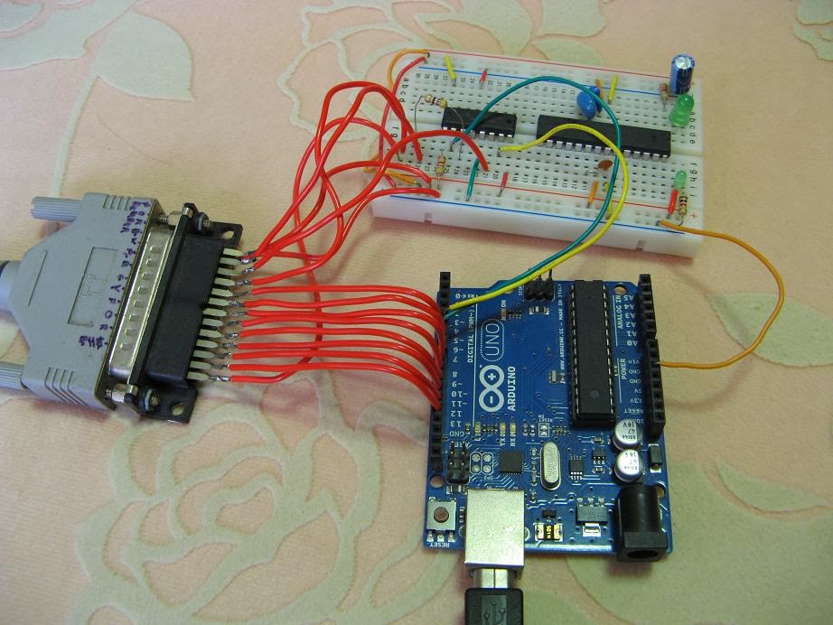
Moving along to the other end of the cable, we arrive at the little breadboard:
There are 8 wires going from arduino pins 6-13 to the enable and phase pins on the motor drivers. The stuff on the top is an H-bridge to drive the pen's up/down motor. Just ignore the other larger chip. It's not related. Arduino pins 4 and 5 control that. This leaves me with two empty pins on that side, which are the interrupt pins and could be used to add limit switches. I didn't add any because, well, I'm optimistic. Remember, you can't, or at least shouldn't, use pins 0 and 1 if you are using the serial port. They are the rx/tx pins.
Here is the schematic for the H-bridge:

One of the arduino pins should be high and the other low. Inverting highs and lows on both will reverse the direction of the motor. Depending on your h-bridge, it may be dangerous to set both the same way at the same time. Be careful.
OK, now you have seen all of the hardware. Let's look at software.
OK, now you have seen all of the hardware. Let's look at software.
The software consists of two programs. One runs on the computer. The other runs on the arduino. The details of the code require a lot more knowledge of SVG file structure, math and programming than I could reasonably include here, so I will just provide an outline and let you figure out the details from the code.
On the computer:
An SVG file contains graphical information encoded into basic mathematical structures such as lines, elliptical curves and Bezier curves, the parameters of which are written in an XML text file. This program scans the file and picks out the path data. It ignores everything else. That means that you will only get lines, which is exactly what a pen is capable of drawing. It then interpolates the curves and generates a list of coordinates which are sequential points along the path. Think of it as a connect-the-dot picture. The precision with which it interpolates curves can be set as a parameter. Also, everything is scaled to a size in mm which is also a parameter. This list of coordinates is then sent via USB to the arduino.
On the arduino:
The coordinates are received by the arduino, which then tells the motors to draw a straight line to the next point. The arduino needs to know the details of the mechanical setup so that it can actually draw straight lines between points. This is accomplished with a little math rather than simple motor speed.
Here are the two parts of code (GNU GPL copyrighted):
SVGReader.pde (computer part) - see processing.org for processing language info
SVGPlotter.ino (arduino part) - written for the arduino ide
///////////////////////////////
OLD FILES: these are no longer compatible with Processing
SVGReader.pde (Depreciated)
SVGPlotter.ino (Depreciated)
///////////////////////////////
63 comments:
Hello friend saw interesting your project and prepared to do the same components used to compile the code and build it as you say to this either stepper motors move if you can not send photos with more detail welded plate with cables ranging from lb11847 to arduino and if not too much trouble processing and arduino original code my email is fmmc_10@hotmail.com
do not send me anything, apparently only friend was a software error because I tried it with processing 2.0 beta 3 and the command executed not probe with version 1.5.1 and it works great discomfort apology and I only need finish it up, and thank you for sharing this fantastic project.
I'm new to the Arduino world and I like your project. Is it possible to change the code for the Adafruit-Motor-Shield or other controllers(L297+L298,TB6560) that use step and dir commands.
I understand the principle, but unfortunately I can see it but not have the knowledge for change in commands for the x/y steppers. Control of pen is simple. Can anyone help.
I am more in hardware than in software...
@ Anonymous -
Yes, it is simple to change this code for other drivers. Look in the function "oneStep()" and alter it to match your driver. This function takes two parameters, the motor number and the direction. Also, change the step size at the top of the code to match your motors. Everything else should work fine.
if you show us how to use ld239d or sn754410 instead of lb11847 for x and y steppers, i will buy a palace from heaven for you.
@ernacati -
A palace from heaven. Interesting.
How much help do you need? Rather than do all the work for you, I will guide you. First, google "bipolar stepper motor". Once you understand how the motor works, you will know what it needs. Then look at the datasheet for your driver chip, the ld239d, sn754410 or whatever chip is convenient. The sn754410 from TI is very nice and the datasheet even has schematics for you (page 6). There are many ways you could use it. The easiest would be to use 4 arduino pins, one for each input on the driver. I will let you figure out the best way to do that on your own, but if you have a specific question, let me know.
Thanks for your reply. And its a saying in my country but you already won a palace :)
i'm trying to understand this ; arduino controlling enable and phase pins on the lb11847 but on the other chips enable pins must be connected logical voltage allways. So if i use only 4 input pins , will i change the code?
@ernacati -
There are different ways to drive a bipolar stepper motor. Here is a site that describes 4-step and 8-step methods. My code uses the 8-step method for higher precision. You will notice that the windings have to be turned off sometimes. This means I need the enable pins. The lb11847 is very convenient because it only requires one enable and one phase pin for each winding. The sn754410 would require one enable and two phase pins for each winding. However, as you see in the schematic in the datasheet, you can use inverting buffers to connect the two phase pins together. If you do that, you don't need to change the code.
If you don't use the buffers, you will need 6 arduino pins for each motor and every time the phase changes you need to toggle two pins instead of one. It is just a small change to the code.
thanks again. its clear now.
hello friend, i tried to implement your project with unipolar stepper motor. i tried to run your processing code and successful to control a servo motor to move the pen up and down. But when the processing send the xdat and ydat data to my arduino UNO, it doesnt do any thing. seeem like arduino do nothing with the digit.
@Jetsen Then -
Thanks for trying the code. There are many possible problems. First, check that the arduino can move the motors. To do this, at the beginning of loop(), write:
"while(1){oneStep(0,1); oneStep(1,1);}"
This should just turn both motors constantly.
If the motors turn, maybe the problem is the parameters at the top of both code files. Make sure they are reasonable. For example, if the processing program is sending an image smaller than the minimum step size, nothing will happen.
If this doesn't help, let me know.
thanks for your reply, i finally can move the stepper motor. I add some delay inside the processing code, then i works. It work correctly when drawing the rectangle but when drawing the triangle, it doesn't close the loop. It move far away from the desired location.
Hello there! I'm doing a plotter too, but I found some difficulties to do hardware. If don't mind, i really appreciate if could answer some questions of mine:
Firt: What kind of cable you're using to do the conversation between board and driver?
Second: There is a kind of adapter in the end of this cable?
Third: It's possible to do this comunication using an USB adapter?
Thank you so much for your time!!!
@Caroline Reinato -
The cable I'm using is an old parallel port cable with one end cut off. I just chose it because it had enough wires for me.
The thing between the arduino and the cable is a bunch of 330 ohm resistors. I put one on each wire just to protect the arduino if something goes wrong. They are connected to a parallel port connector from an old computer.
What do you mean by "USB adapter"? the arduino is communicating with a computer via USB. But the motor driver doesn't speak USB, so you couldn't connect it directly.
Hey, thanks for your answer!
The driver that i'm using is from a Hp multifuncional. It's connect with computer by a USB type B. I found on Internet a cable that convert the paralell port to USB; just like on this link:
I just buy this cable, so I don't test it yet to know if the program .ino will works. Soon as I can test it, I'll be in touch to tell if it worked or not.
Your blog it's been very useful! Congrats!!! Thanks for share it with us!
Ops, I could not post the link =/
Hi, i'm trying to make this project because it's what I need and I didn't know so much how to develope the program in Processing.
I downloaded your sketches, but Processing says " cannot find a class or type named "FileReader".
Could you help me?
Thanks, Alberto.
@Alberto Perro -
I guess that means you don't have the Java libraries on your computer. FileReader is a class that may not come with Processing, but it is in the standard Java libraries. You could download and install the Java JDK(I think that's what it's called) which puts all the Java libraries on your computer and makes Processing much more useful since you can use any Java class directly in your processing sketches. This may require reinstalling Processing, but that's not hard.
If there is still a problem, let me know.
Hi,
I found a small mistake in your SVG Parser.
For splitting the tokens you used
pdata = splitTokens(pstring, ", TAB");
The problem is that TAB will be used independent letters.
So T will be a seperator for itself as well as A and B.
I found this when loading a SVG with and Arc (A) which then caused problems.
I suggest fixing this by using
pdata = splitTokens(pstring, ", \t");
Thanks for the code.
@Anonymous -
Thanks for noticing that. I can't imagine why I would write TAB instead of \t. I must have been really tired while writing that part.
Hi,
Thank you very much for sharing your code. I've been trying to implement it, but I'm having some troubles in the communication between Processing and Arduino. I receive "timed out" or "didn’t send data" errors in Processing.
So far, I have tested with the "while" instruction with the "onestep" function, and the motors run correctly, and I have set the motors step size according to my motors.
Could you please help me out to find out what could be the reason that I get the errors?
These are my parameters in the Processing file:
final double precision = 0.5; // precision for interpolating curves (smaller = finer)
final double maxdim = 350.0; // maximum dimension in mm (either height or width)
final boolean sendIt = true; // true=sends the data, false=just draws to screen
These are my parameters in the Arduino file:
const float stepSize[2] = {0.000375, 0.000375}; // mm per step [x, y]
const int fastDelay[2] = {1, 2}; // determines movement speed by
const int slowDelay[2] = {3, 6}; // delaying milliseconds after each step
When I run the code in Processing, this is the result that I get in the console:
subpath complete, points: 6
total points:6
Stable Library
=========================================
Native lib Version = RXTX-2.1-7
Java lib Version = RXTX-2.1-7
sent N:0 X:262.11427708315995 Y:343.93203480532026
timed out / didn’t send data
(Sometimes I get a "timed out" error, and other times I get the "didn't send data" error)
@Ariel -
Thanks for trying the code. It sounds like a communication problem between the computer and arduino. Those messages both mean "timed out" , but I forgot to change one for some reason. After the computer sends data it waits for a confirmation from the arduino. "timed out" means that the confirmation never came, but since you seem to be getting the first point ok, I think it might be a speed problem. Try lowering the serial rate in both arduino and processing sketches.
Sorry, this code was kind of hastily written and not extensively tested. Let me know if you run into any other bugs.
Hello and thanks for such a quick answer!
I've lowered the serial rates in arduino and the processing sketches, and I got the motors moving. However, Processing managed to send up to 3 the points (I have a total of 6 points for this sample file.
Is there anything else that you think may be affecting it?
Thanks again for the help.
Ariel
@Ariel -
If slowing the serial rate improved it, there is some communication problem. You will have to find that problem on your own, but I'll give you some ideas.
The error occurs when the arduino takes too long to send a confirmation byte after receiving a number. The arduino has two conditions that must be met before it will send the byte.
1)The character '.' must be sent from the computer signaling the end of the number.
2)The serial buffer must be empty, i.e. Serial.available() == 0.
Also note that the time limit is three seconds, which is more than 2.9 seconds longer than it should normally take. In other words, I'm pretty sure the arduino is not meeting one of the conditions above.
This could be caused by the serial buffer overflowing or the transmission being physically corrupted. Do you have any idea how many digits are being sent for each number?
Try some simple communications tests, like sending the arduino the data and after a second the arduino sends the same data back. Then compare the returned data to see if anything was lost.
Good luck. Let me know if you need any more ideas. Just glancing over the code now I can see several things I would do differently. If only I had time to update it.
Hey there! I have a plotter but it runs on 3 micro servos...how can I modify or rewrite your code to make them go?
...and I will get you a hot tub in heaven
@Frank enStuff -
Thanks for the hot tub.
X and Y axes are easy. There is a function called:
void oneStep(int m, int dir)
Where m is the motor(or servo) and dir is the direction. All you need to do is change this function to move your servos by one "step". I'm not sure how you are driving your servos, but it shouldn't be hard to modify this one function. I'm not 100% sure, but I think all the rest of the code will work as is. Of course you will have to calibrate things and figure out how far one "step" moves your plotter and how fast the servos can move.
For Z axis, you will need to do a bit more work, since I just turned on a DC motor for a few millis and there is no stepping. Good luck.
Hi..I got this working using Processing 1.5.1 but now I'm trying to use Processing 2.1 with no luck. I added "import java.io.*;" to fix one problem but now I'm having a communication error. The image is processed, as I can see when I set sendIt false, but I get a time out error when sendIt is true. Any ideas on what v2.1 doesn't like?
@Anonymous -
Hmm... I have no idea what's wrong. I haven't used the new version and I haven't really looked at this code in a long time. I'll give you some advice if you haven't already figured it out.
First, find some simple example code that uses serial communication to talk to an arduino. Then figure out what is different between that code and mine. Try to modify the communication parts of my code to match the working example.
hola! me again! I just tried running the code and got this as an error
"br=new BufferedReader(new FileReader(file));"
I know you havent looked into the code at all in a while but....for somone like me this is a great starting point. I havent found any other projects with the arduino code and processing code to make things go. I am just trying to make a simple plotter. I gave up on the servos because of strength and accuracy, now I have some of those little 5V stepper motors....but still havent gotten a frigging thing to move. just nuts. I spend too much time looking into other peoples projects and you make it look so simple, but when I go - its like there is a secret code to the codes code.
@frank enStuff -
OK, I'll see if I can help.
I just downloaded the latest version of Processing and indeed got an error: "Cannot find a class or type name "FileReader"
*30 minutes of looking over the Processing reference and trying things*
It seems that Processing has changed a lot. The new way to use a BufferedReader is like this:
br = createReader(fileName);
Then delete the lines about FileReader and File.
I don't have time to work on it more now, but if this doesn't fix it, I'll try again later.
@frank enStuff -
Good news. I've changed both pieces of code. The processing sketch is now compatible with Processing 2.1.1 and supports more SVG features.
The code is not uploaded here yet, but I'll get that done within the next few days.
NOTE:
I have updated the code and made some small changes to the hardware. See above.
@Kevin Groce -
I think it was a stylus color 680(that's the service manual I was using). It was probably 10 years old, so I doubt you would find the same one.
What is the paper sheet dimension that is supported, can it write on roll paper?
very good contribution! I would like to deploy it to a drawing robot, which uses two unipolar motors and a rope with a marker. but I'm new to arduino and causes me difficulty change the using onestep accelstepper to use the moveTo
Very cool. I got a hold of an old plotter with only the two steppers remaining. I'll add some easydrivers and some sort of control for the penholder (requries ~14V to click it into writing position).
Two comments so far: You have mixed up the links for the pde and ino-files (the pde points to the ino and vice versa).
I'll be using the limit switches on my plotter, but I notice that you nowhere specify a maxrange for X and Y, so the plotter will place the center in the middle of where it started from and x/ymax - this could be ok if one remembers to manually position the pen in the opposite corner before turning it on (as I see if, I might have overlooked something).
On many 3D-printer, the X and Y limit switches are placed in the bottom,left (home) position, and the center is found from there (with maxrange for x and Y specified in software), which I might modify the software to do as the limit switches for mine are placed bottom/left.
Cheers!
Shoot. Nevermind, I looked in gohome() and here you actually do zero it in in the bottom left.. still leaves me to having to hack the code a bit as I've only got limits at bottom/left, but hey.. :)
poor little dotmatrix :'-(
Hi. Just want to thank you for sharing this project. I've manage to make it work with Adafruit motorshield v.2 and processing 1.5.1. and it's working real fine.
I am really grateful and i you don't mind i'll call it "The Heisler plotter" :)
@Tommy Frank -
Great! I'm glad it worked for you. Let me know if you make a cool project with it.
I wonder where my name is on this page.
Hi. I'll let you know. Regarding your name then you're welcome to edit it out if it's inconvenient for you to have it to appear here. I noticed it in a copyright note in a sketch and assumed it was you.
Hi! I see you're doing a fine work there! I just have a question: Don't these motors work with 45v? I saw the datasheet for the LB11847, and this voltage must be connected to the pin 14. However, in your schematic pin 14 is just connected to +5v...
How are you feeding the circuits? Thanks a lot, i'm trying to do the same as you!
@Emanuel Reynoso -
In the printer the motors are driven by a higher voltage, but all of the hardware will work fine at 5V. The motors will have a lot less torque and will need to be driven more slowly, but they will still work. I only chose 5V to keep things simple with one power supply. If you are doing a similar thing, you could use the printer's power supply which would have both 5V and a higher voltage rail for the motors.
bipolar stepper driver L293d or L298 onestep() code;
(dont forget to chance pin number to your board design)
void oneStep(int m, int dir){
// make one step with motor number m in direction dir
// then delay for useDelay millis
// e1=A p1=B e2=C p2=D A<--coil1-->B C<--coil2-->D
// 0=+--- 1=--+- 2=-+-- 3=---+ (wave drive - one phase on)
if(dir > 0){
poss[m]++;
posmm[m] += stepSize[m];
if(mstate[m] ==0){
digitalWrite(e1[m], LOW);
digitalWrite(e2[m], HIGH);
mstate[m] = 1;
}
else if(mstate[m] ==1){
digitalWrite(e2[m], LOW);
digitalWrite(p1[m], HIGH);
mstate[m] = 2;
}
else if(mstate[m] ==2){
digitalWrite(p1[m], LOW);
digitalWrite(p2[m], HIGH);
mstate[m] = 3;
}
else if(mstate[m] ==3){
digitalWrite(p2[m], LOW);
digitalWrite(e1[m], HIGH);
mstate[m] = 0;
}
}
else{
// e1=A p1=B e2=C p2=D
// 0=+--- 1=--+- 2=-+-- 3=---+
poss[m]--;
posmm[m] -= stepSize[m];
if(mstate[m] ==0){
digitalWrite(e1[m], LOW);
digitalWrite(p2[m], HIGH);
mstate[m] = 3;
}
else if(mstate[m] ==3){
digitalWrite(p2[m], LOW);
digitalWrite(p1[m], HIGH);
mstate[m] = 2;
}
else if(mstate[m] ==2){
digitalWrite(p1[m], LOW);
digitalWrite(e2[m], HIGH);
mstate[m] = 1;
}
else if(mstate[m] ==1){
digitalWrite(e2[m], LOW);
digitalWrite(e1[m], HIGH);
mstate[m] = 0;
}
}
// Wait a bit
delay(useDelay[m]);
}
yunus
in SVGReader2.pde
// wait for z axis calibration
boolean zcal = false;
change the zcal to false
because;
SvgPlotter2.ini dont send any 'Z' char, proceses wait wait.. finally time out and dont print anything
yunus
@Anonymous -
Thanks for that. The calibration method depends on the hardware. I was actually setting the calibration(zcal) by pressing buttons, so there should be no 'Z' command sent automatically. Sorry if that caused you any headaches.
First of all, thanks for a great project!
I've been trying to use the code simply to translate SVGs into coordinates via Processing, but I keep getting the same error over and over again, which is:
total path points:0
total drill points:0
There was an error in the data file
I've exported to SVGs by both using Illustrator and Inkscape, but nothing seems to work.
Have you, or anybody else, experienced the same problem as me and know how to solve it?
@Ejrik -
If you upload your svg file somewhere I'll take a look at it. The message "there was an error in the data file" is there because there was no path data found. It is possible that your image contains only path elements that are not supported.
@ME
I've tried a a lot of different SVG files, but here's one of them at least: http://www.filedropper.com/img01
Thanks for quick answer!
Okay, I managed to make it work on some level. I created an SVG file with a lot of different shapes - rectangles, circles, spirals, stars etc, with both premade shapes tool and pen tool in Illustrator.
However, the only shape that's displayed when i hit "Run" in Processing is the rectangles from the premade shape tool.
Does every other shape contain quadratic Bezier curves and is therefore not identified? Is there a way to make the "not" based on bezier curves?
Cool!
I have seen your videos on Youtube. I think that you could use the experience gathered from the "line following robot", the ATtiny10 friend and the plotter to make a contour tracer and a template maker (the plotter). There are a few systems that cost as much as a new car:
Check out the PRODIM digital templating or "touchstone instruments" template digitizer
I am sure that you will find a wired or wireless device that can record its position with precision. Trust me, you can do it!
If you want to assemble identical copies, you will need to cannibalize new items that are still being produced and can be purchased at wholesale prices. That way, the day after you complete a working prototype, you can assemble ten more.
It does not matter how much it cost you to build because the models that are on the market cost around $30,000.
I need a contour tracer that can duplicate the perimeter profile of a restroom floor. It takes me a lot of time to make a template with paper and tape. Last night I found a cheap instrument that could give me a perimeter profile template. I am sure that a 3Doodler can be used if water is sprayed along the wall floor contact line to prevent the plastic from sticking. Additional line could be needed to maintain the true shape. I will then have to cut the linoleum by hand without a plotter.
I only wish that I had your knowledge of new technologies because I know how to recycle the labor input out of man-made objects. Thank you for posting your videos. PRPaul1
Hi, I'm working for a project for school and I was interested in using your code to get x and y coordinates that I then myself can use to program the arduino, but what exactly does the computer send to the arduino? Is it just (x,y)? or is it more? And I'm kinda new to this and its all so complicated :( Thanks in advance Nicholas Parmentier
https://6iwgpgraveermachine.wordpress.com/
Can I have some help with changing the code to make it work with the Adafruit motor shield v2? I don't know how to. To base my code all I have is the Adafruit exemples library, and it seems like we talk to the motors directly instead of pins? How do I change the code then?
Thank you!
Thank you for sharing, it's really helped me...
Very nice article...
I like this article, can add knowledge to every person who read it, thanks
How to use code to read a .svg file? And please update the code to be compatible with Processing 3.0.1. Thanks in advance.
All the files on Google drive could not be downloaded.
Please provide another working links. Thanks.
I keep on getting the following error:
"connected, but with error"
when trying to run the .pde file, and it eventually just times out.
I have set zcal equal to false as mentioned above, and I am using processing 2.1.1. I also tried to read through the bytes I was receiving, but I wasn't able to make sense of any of it. Would you happen to have any suggestions to help in my troubleshooting?
I actually got the arduino to connect by changing the baud rates to 115200, but the program is still timing out in the while loop in the sendNumber function. Any suggestions?
my trouble is solved, thank you for information
Hello there! Thank you for sharing your blog with us. I'm so glad to find this blog.
Printer Maintenance Service
Post a Comment